Demo-Modular Piping
Tutorial content
This tutorial aims to provide a detailed explanation of the Amesim documentation from a beginner's perspective, elaborating on the logic and key points, in order to help users better understand and get started.
Software Version:Amesim 2021.1
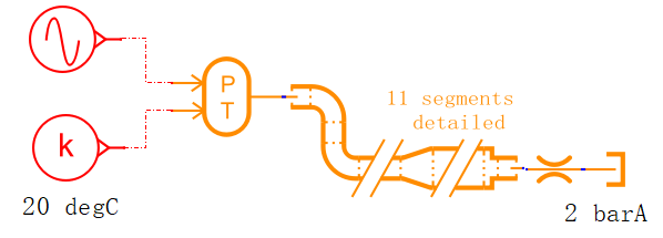
As shown in the figure below, this is a pipeline composed of straight pipes, sudden change interfaces, 90-degree elbows, and gradual expansion pipes. Calculate the flow characteristics under given pressure and temperature. Through this case, you can learn how to use the pipeline modeling tool built into Amesim to flexibly create complex multi-segment pipelines.

Modular Piping tool
Create the model as shown in the figure
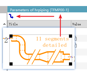
The main model is the TFMP00-1 in the middle. Click on it, and there is a small blue icon on the left. Opening it will reveal the tool for creating pipelines.
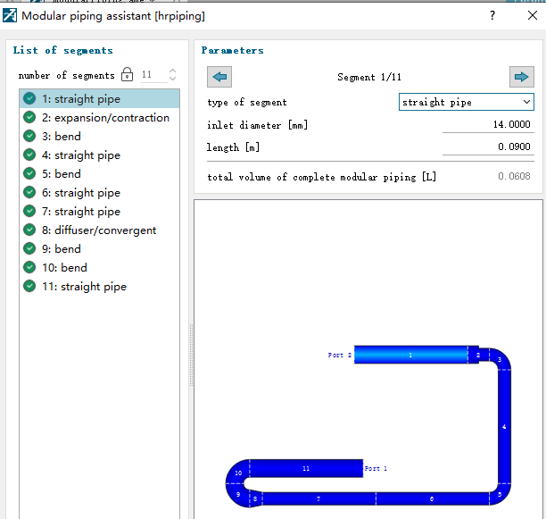
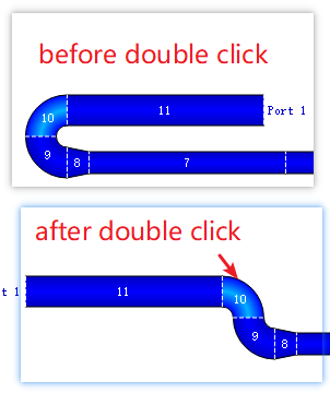
The interface of the pipeline assistant is simple and intuitive. It can mainly create straight pipes, elbows, reducers, expanders, and elbows with sudden change interfaces. The detail to note is that you can double - click on the component to adjust the direction, as shown in the figure below.
If the diameter of the pipeline is set incorrectly, the software will also give a prompt, which is quite intelligent.

Equivalent model
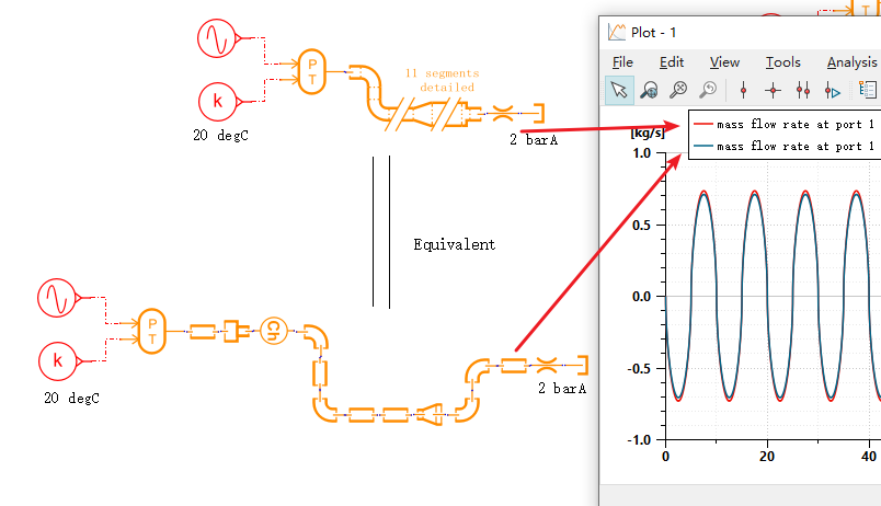
Modeling tools only simplify the creation process of complex pipelines. It is equivalent to the model shown in the figure below.

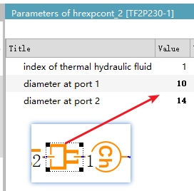
To illustrate the equivalent process, let's take an example. For instance, consider the No. 2 pipeline at the beginning, where there is a suddenly contracting cross - section.
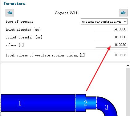
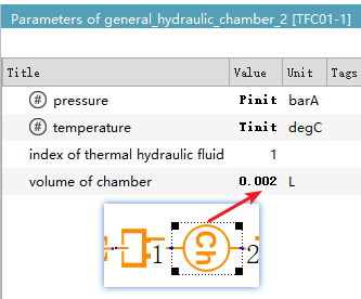
It is equivalent to a sudden contraction interface element and a volume element connected in series, with exactly the same parameters.
Run simulation
The results show that the export flow rates are basically the same, indicating that the two models are completely equivalent. However, it can be seen that the modeling workload of the lower model is greater, the parameter settings are more complex, and there is no complex graphical interface for easy observation. More importantly, if the pipeline parameters are set incorrectly, it is not easy to intuitively troubleshoot. Therefore, if there is such a complex pipeline, it is recommended to use the pipeline modeling tool to create the model.
Complexity switching
The pipeline model also provides a parameter that can control the complexity of the pipelines created by the modeling tool, including the detailed mode and the simplified mode.
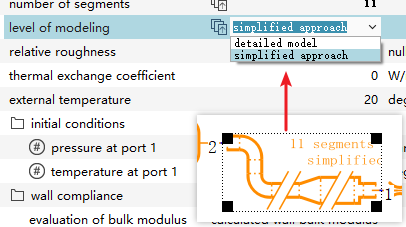
Detailed mode: All pipeline components (straight pipe sections, direction changes, diameter changes) are considered separately. Each section along the pipeline is modeled as an R-C component, and state variables are added for each singularity (diameter or direction change) and pipe section to represent the internal pressure and temperature. The calculation accuracy is high, which is suitable for local analysis of complex pipelines. However, the calculation time is long, and it is suitable for obtaining the pressure and temperature distribution section by section.
Simplified mode: Calculate the global pressure loss coefficient, regard the entire pipeline as a single module, and do not consider each component separately. The accuracy is slightly lower, but the calculation time is much faster. It is suitable for rapid simulation, such as estimating the pressure loss in the preliminary design stage of the system and evaluating the overall performance of large-scale pipe networks.