Signal Component-SIGTRGSIN0 -triggered sine wave generator
Tutorial Content
This tutorial aims to provide a detailed explanation of the Amesim documentation from a beginner's perspective, elaborating on the logic and key points, in order to help users better understand and get started.

This component itself is quite simple. The reason for discussing it is that apart from having variable frequency and amplitude, it also provides a Trigger input option. Trigger is used in many places in Amesim. Therefore, understanding and mastering the concept of Trigger through this component will help in understanding the role of Trigger in other more complex components or scenarios.
The following will introduce each function of the component one by one.
Function 1: Variable Frequency
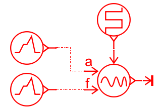
Build the model as shown in the figure below. The frequency and amplitude are controlled by piecewise functions. First, look at the variable frequency function.
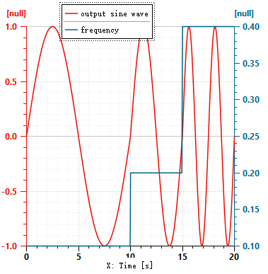
The blue line in the figure below represents the frequency f, and the red line represents the output sine signal. The settings are as follows:
- From 0 - 10s, f = 0.1HZ, so the first sine wave lasts for 10s.
- From 10 - 15s, f = 0.2HZ, so the second sine wave lasts for 5s.
- From 15 - 17.5s, f = 0.4HZ, so the third sine wave lasts for 2.5s.
- After 17.5s, since there is no setting for f, the subsequent sine signal maintains the frequency of the previous stage, which is 0.4HZ. Therefore, from 17.5 - 20s, another sine wave with a duration of 2.5s appears.
Function 2: Variable Amplitude
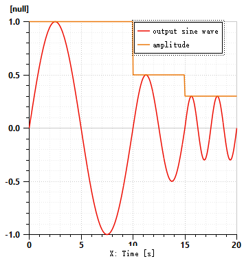
Based on the previous figure, change the amplitude to the piecewise function shown in the figure below.
- From 0 - 10s, the amplitude is 1, so the amplitude of the first sine wave is 1.
- From 10 - 15s, the amplitude is 0.5, so the amplitude of the second sine wave is 0.5.
- From 15 - 17.5s, the amplitude is 0.3, so the amplitude of the third sine wave is 0.3.
Function 3: Trigger
To understand Trigger, it is best to not consider the variable frequency and amplitude first. Otherwise, it will be difficult to understand when they are mixed together.
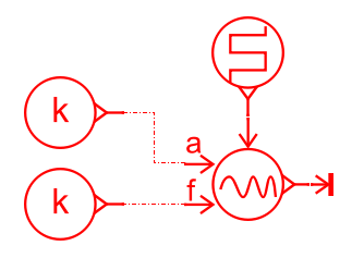
Establish a new model, set both the frequency and amplitude as constants, and focus on studying the role of Trigger.
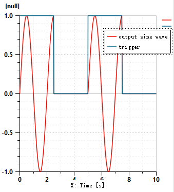
As can be seen from the figure, when Trigger is 1, the signal is continuously output, and when Trigger is 0, the signal output is 0.
Parameters of "wait for end of cycle"
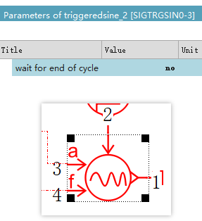
The component has a parameter called "wait for end of cycle".
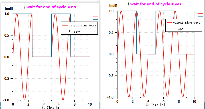
From the figure below, we can see the differences between setting "wait for end of cycle" to "no" and "yes".
- When set to "no": Forcefully truncate and set the output to 0 regardless of whether the cycle has ended.
- When set to "yes": Wait until the previous cycle is completed, and then start truncating and set the output to 0.
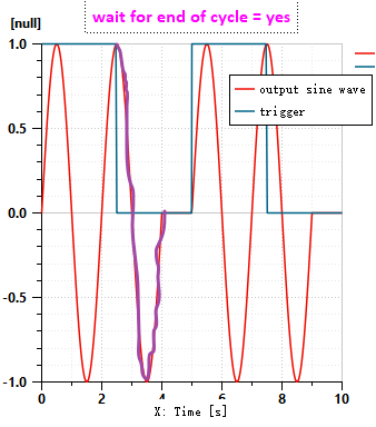
The "end of cycle" refers to the section of the curve that I manually traced in the figure below.
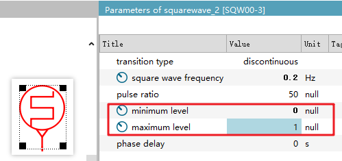
Parameters of the Trigger Signal
The Trigger signal only serves a control function, and the help documentation does not specify what format the input Trigger must be in, nor does it explain what effects the high and low levels correspond to.
Therefore, it is recommended to maintain the default values of 1 and 0 for the high and low levels.
I've tried adjusting the values of the high and low levels, and the output signal may change. For example, in the figure below, when the low level is 0.4, the output is normal. However, when the low level is set to 0.6, the low level no longer functions.
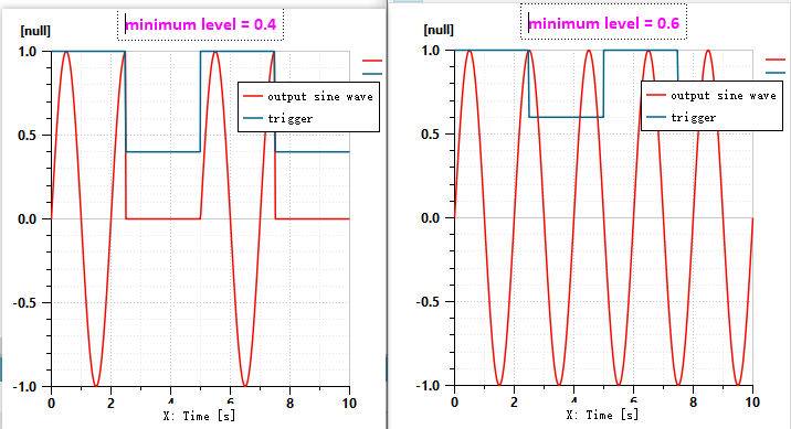
That's it!