Signal Component-LAG1-First order lag
This tutorial describes the usage of the first order lag model of the signal library
![]()
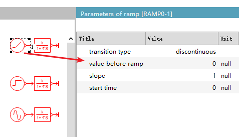
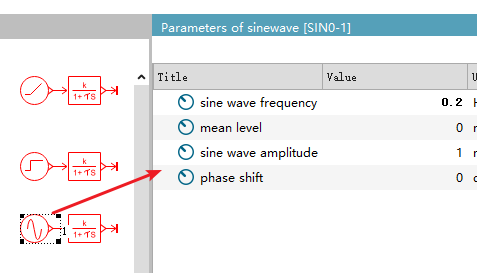
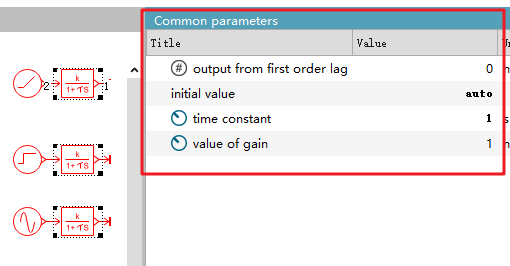
I have set up three cases. Three different input signals are given on the left. After first - order lag processing, let's see what the output signals become.
Understanding these three cases means understanding how to use this component.

Model parameters
Select three first - order lag models and set the same parameters
Time constant
The first - order lag model is used to lag the input signal.
For example, when the motor speed is set to 3000 rpm, the motor speed will not reach 3000 rpm instantaneously. It takes a certain lag time to rise to 3000 rpm.
The first - order lag model is used to control the speed of this lag time. The most important parameter here is the time constant.

The time constant refers to the time required for the system to reach 63.2% of the steady-state value from the initial state. If it is 1s, it means that the system reaches 63.2% of the stable value in 1s. If it is 0.1s, it means that the system reaches 63.2% of the stable value in 0.1s. Evidently, the smaller the time constant, the faster the system response speed.
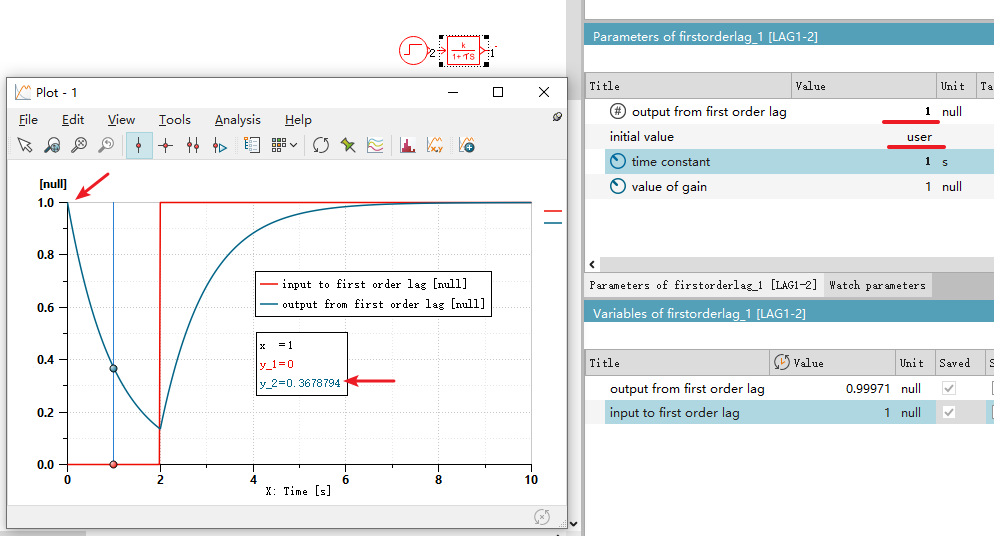
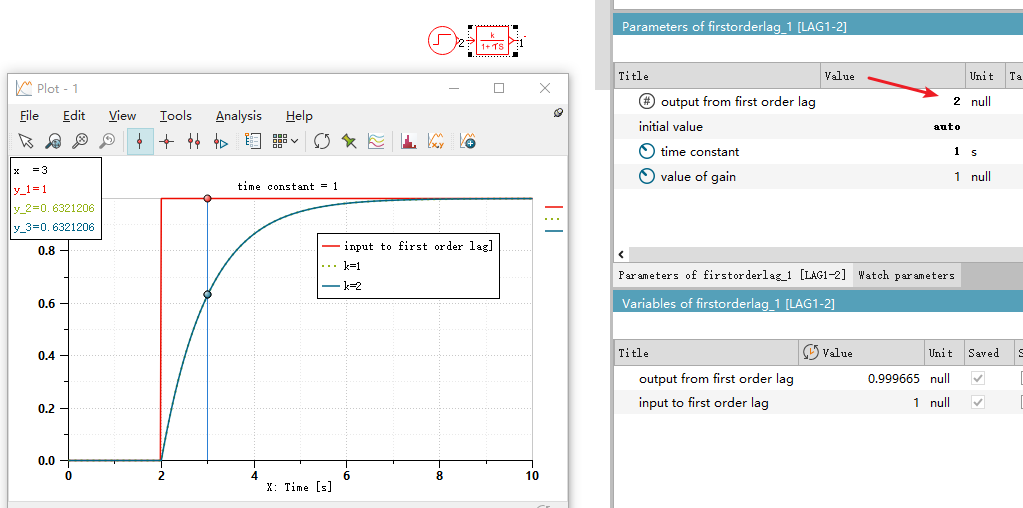
When running the simulation, you can observe that the red line represents the input value, and the blue line represents the output value. The output value lags behind the input value.
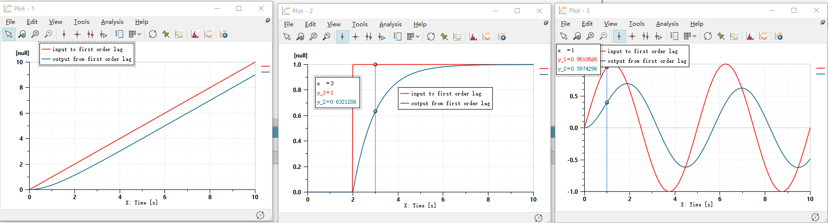
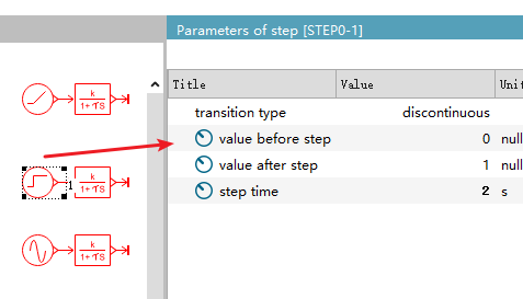
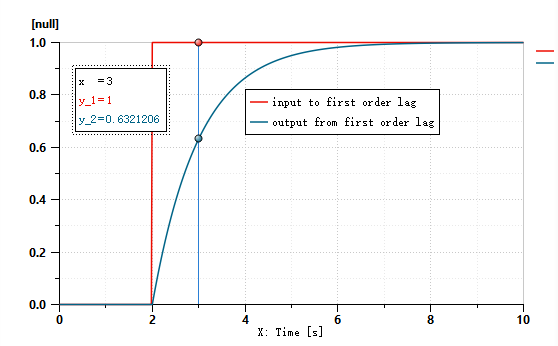
The model in the middle is the most intuitive for understanding the usage. Let's focus on studying the model in the middle.
It can be seen that when the input value becomes 1 at 2s, after 1s, the output value just becomes 0.632.
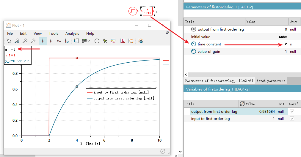
Changing the time constant to 2, it is found that indeed at the 4th second, the output value just becomes 0.632.
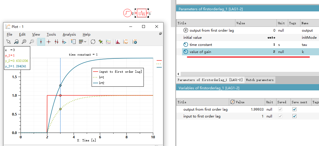
value of gain
Adjust the time constant back to 1. Try adjusting the gain k to 1 and 2 respectively. As can be seen from the figure below, at 3s, the output of k = 2 is exactly twice that of k = 1.
1.26 = 2 X 0.632
initial value
There are two options for the initial value. When it is set to "auto", regardless of the value set for "output from first order lag", the initial value is the same as the input value.
However, when the initial value is set to "user", setting "output from first order lag" to 1 starts to take effect. As can be seen, the initial value of the output is 1. And since the input value is 0 from 0 to 2 seconds, the output value will lag and become 0. At 1 second, it just changes from 1 to 0.378, which is approximately 63.2% of the way.