Thermal Demo-Concentric Cylinder
Tutorial Content
This tutorial aims to provide a detailed explanation of the Amesim documentation from a beginner's perspective, elaborating on the logic and key points, in order to help users better understand and get started.
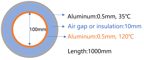
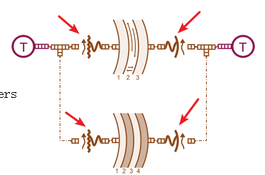
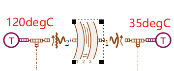
As shown in the figure below, this is a case where two aluminum tubes are concentrically nested together. The dimensions and temperatures are as shown in the figure. The objective is to determine the heat transfer characteristics when the material in between is either air or fiberglass.
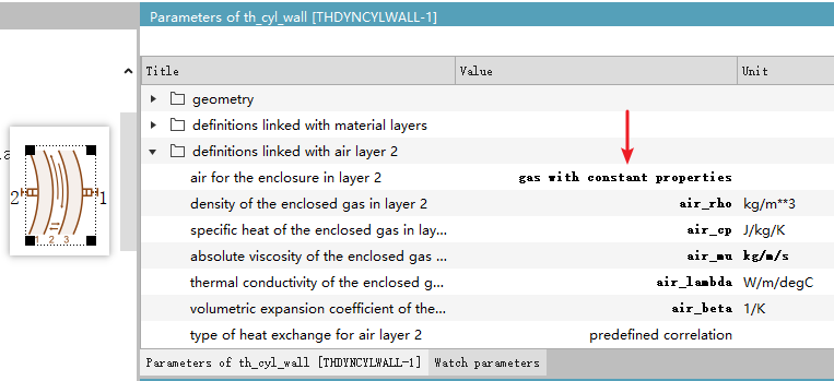
Question 1: Why is the air material set to "Gas with Constant Properties"?
When you open and check the parameters of each component, most of them are not easy to understand. But why specifically choose "Gas with Constant Properties" for the air material? When I first looked at this case, I was also totally confused. I just wanted to learn about heat conduction in an aluminum tube—why do I need to understand so many air-related parameters?
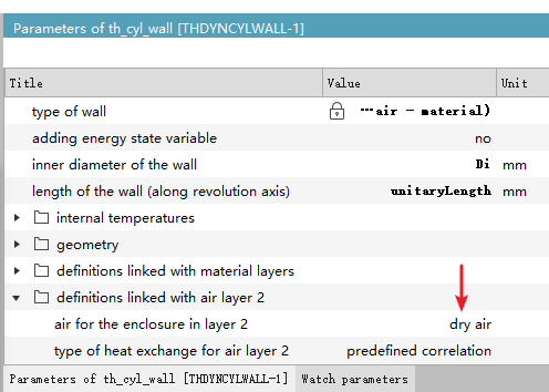
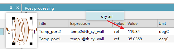
Let’s take the simplest approach—don’t worry too much about it for now. Just change the material to dry air and see what happens.
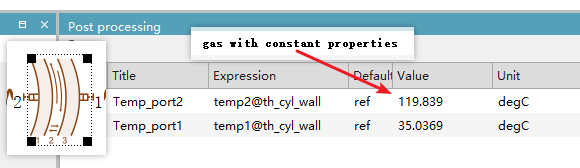
From the results, you can see that no matter which material definition you use, the simulation shows almost the same temperature at both ends of the aluminum tube. Therefore, for custom materials, we can consider this to be merely an example provided by the official documentation to illustrate the feature. In regular simulations, if the requirement for air property accuracy isn't very high, using the default dry air setting is sufficient.
Question 2: Why are there four extra components?
It seems like this should only involve heat conduction in an aluminum tube, so why does the model include four additional components? It feels unnecessarily complex.
Let’s simplify the case first and build the most basic model—only using two end caps to seal both ports. This matches more closely what a beginner might imagine when seeing this case.
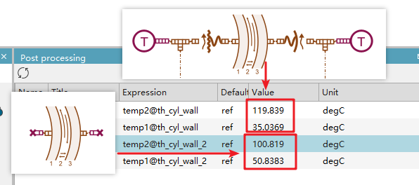
After running and comparing the results, we observe that with only the end caps sealing the system, the internal temperature doesn't remain at 120°C but drops to around 100°C, while the external temperature rises from 35°C to approximately 50°C. This indicates a temperature difference due to heat transfer between the inner and outer sides.
However, in the official example, the temperatures are basically maintained at 120°C and 35°C.
Therefore, we can conclude that these four additional components are simply used to provide heat sources, ensuring stable internal and external temperatures.
Question 3: What is the difference between skin temperature and mean temperature?
When setting up this component, what is the difference between skin temperature and mean temperature?
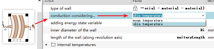
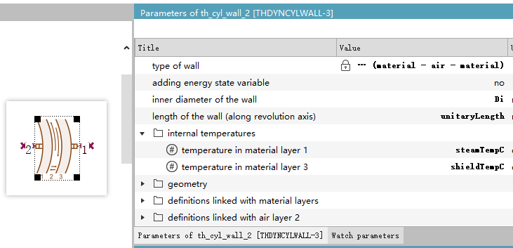
According to the official diagram explanation, each “material layer” has its own temperature. The calculation of heat conduction between two “temperature points” depends on the distance between those points. Skin and mean are options for determining whether the temperature point of each “material layer” is located at its center or edge, as illustrated below:
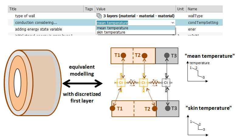
Frankly, this concept is still somewhat difficult to grasp fully, and this particular case doesn't clearly demonstrate the distinction. Here's my understanding:
mean temperature
Refers to the average temperature within a material layer. In thermal modeling, the corresponding temperature point is located at the center of the material layer. With this setting, during calculations such as heat conduction, the assumption is made that the temperature distribution across the layer is uniform, and the average value is used. This approach emphasizes representing the thermal state of the entire layer from an overall average perspective.
skin temperature
Refers to the temperature at the edge/surface of the material layer. During thermal modeling, the temperature point is positioned at the layer’s boundary. This setting considers the surface temperature of the material layer. In some thermal analyses, when surface heat exchange significantly affects the overall thermal process, surface temperature is used for related calculations and analysis.
When conducting your own simulations, the choice between the two settings should depend on careful analysis of your model. You may even want to try both and analyze the results alongside physical phenomena to decide which one to use. For this particular case, there’s no need to overthink this issue—just understand that these are two different approaches for handling discretization problems.
Question 4: Why are different numbers of layers used for the aluminum tube?
Why is the material defined as three layers when the middle layer is air, and four layers when the middle layer is fiberglass?
Similar to previous articles on plate heat conduction, the two middle layers essentially represent a discretization of the fiberglass material into two units, thereby improving computational accuracy.

Question 5: Why are two heat sources set up?
Since the aluminum tube is hollow, heating can occur both internally and externally, meaning there are two ports available for setting internal and external heat sources.
The numbering of material layers starts from the innermost layer (layer 1), increasing outward. The component icon also indicates the layer number. Therefore, port 1 corresponds to the outermost layer, where the temperature is set to 35°C, and port 2 corresponds to the innermost layer, where the temperature should be set to 120°C.
Other Notes
The above covers the main difficulties and questions in this case. The remaining geometric parameters and temperature settings for the aluminum tube are relatively straightforward—simply opening and checking them will make things clear, so they won’t be discussed further here.